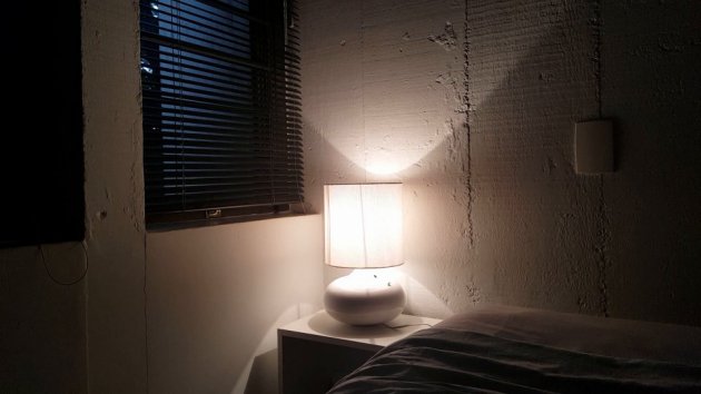
It was early December in 2015 and Christmas was just around the corner. I wanted to give my girlfriend something nice as a present, and that’s when I stumbled across this Gizmodo article hailing how a wake-up light had changed their life.
The basic idea is a bedside alarm clock that instead of buzzing loudly, wakes you up by gently increasing the brightness in your room. The increase in brightness gradually inhibits the production of melatonin, our main sleep hormone, gently pulling you out of deep sleep. As a result, you wake up less groggy, more energized and ready to tackle the day.
My girlfriend has always had a love-hate relationship with the alarm clock. I was on to something.
Then it struck me – why not build it? Why not make a present and have some fun (and not much sleep) while doing it, right? Of course, “having fun” usually means over-engineering things a bit 🙂
The Laundry List Of “Hell, Why Not” Features
- Sunrise simulation (the main feature)
- Smartphone controlled via WiFi
- Can be used as a (digitally) dimmable bedside lamp
- Sound activated, turns on and off by clapping (yes, really)
- Automatic network time synchronization
- Automatic address resolution (mDNS)
- Easy WiFi set up (captive portal)
- Beeping as a failsafe wake-up alarm and audio feedback
- A hidden morse-code message as an easter egg (geeky girlfriend)
- Doesn’t burn down your house and kill you in your sleep (VERY IMPORTANT)
Disclaimer
 As usual, PLEASE be very aware that I cannot guarantee your safety if you attempt to replicate this project. This project is particularly dangerous because it involves AC current, so if you’re not comfortable and experienced handling it, please don’t attempt. While I have exercised safety to the best of my knowledge, there might be project flaws here that could expose you to dangerous electrical shocks and even fire. Having said that, the lamp has been functioning for over a year without any incidents. If you see anything that should be corrected, please let me know. During the course of this post I’ll talk about the safety provisions that were made.
Overview
So, let’s tackle it in smaller parts. The first thing I should mention is that the brains of the lamp is, once again, the mighty ESP8266. It’s really amazing how much bang for your buck you can get with this thing. I’ve used it before to “Internet enable” my blood pressure monitor, check it out if you haven’t yet. Here is a block diagram of sorts: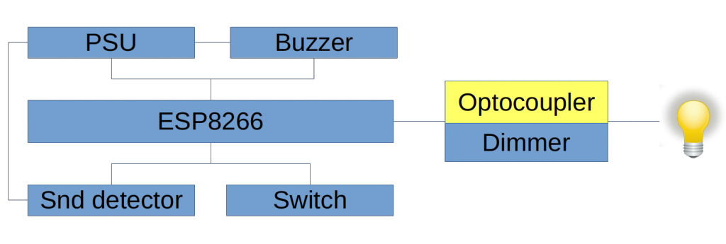
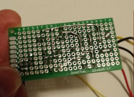
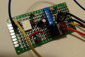
I was short on time, so I tried to use things I had in my parts bin instead of building everything from scratch.
The Power Supply
The power supply is nothing fancy, just your run-of-the-mill switched power supply. In comes 110-220 VAC, out goes 3.3 VDC. I probably got this one from AliExpress for a few bucks, but there are endless options to choose from. Make sure it’s relatively low noise and has good filtering. Noisy power supplies can be a big source of frustration. Also, make sure it has isolation, meaning it uses a transformer, which is an important safety feature. It creates an air gap between high voltage AC coming from the power grid and our circuit. The power grid can be very unpredictable, subject to lightnings and other failures. This particular power supply also has over temperature and over current protection, which is also nice.
The other, VERY IMPORTANT thing to use is a POWER FUSE. It’s the first thing between the whole circuit and your AC mains. This is crucial, dirty cheap insurance. Contrary to what some people might think, the purpose of a fuse is not to protect the equipment, but to protect YOU. The fuse will blow in case something wrong happens and the equipment starts drawing an excessive amount of current. That will help prevent heat build up and a possible fire. Always replace fuses with the correct value. I used a 0.5A fuse which stands up to 110W at 220VAC.
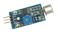
The Sound Detector
The sound detector is a little module I got from dx.com that is basically a microphone and a voltage comparator. It will output a signal whenever the sound amplitude is over a certain threshold that you set using the blue trimpot.
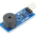
The Buzzer
The buzzer is an active buzzer module (also from dx.com) that buzzes really loud when you feed it a high signal. Being active is nice because we don’t need PWM to generate a tone, and we need PWM for the dimmer.
The Dimmer
If the ESP8266 is the brains of the lamp, the dimmer is the heart. This is the thing that pumps current to the light bulb. You can think of it as a very fast switch. Some of the time it is off, some of the time it is on – that is called duty cycle. If it is on 50% of the time, you have 50% of the power.
High Frequency Switching Vs Zero Crossing Detectors
This circuit is different from regular dimmer circuits. Dimmers normally have zero-crossing detectors, which detect when the AC waveform crosses 0V. That gives them a reference point, from which the dimmer delays switching on the circuit. The wave form crosses 0V twice every cycle (positive and negative parts), and at 60Hz, half a wave form lasts a little over 8ms. That means if you delay for 4ms after detecting 0V you will get 50% of the power. The thing with this kind of circuit is that it is quite a bit more complex, especially if you want to control it digitally. You need the zero-crossing detection circuit and you also need to feed that signal back to a microcontroller, so that it can trigger the necessary delay at the right time. That’s a lot of CPU interruption.
But we can do it differently: we can simply “chop” the AC wave form at a high frequency. If we do it at a frequency that is at least twice that of the original wave, we can avoid producing low-frequency aliasing without needing the reference provided by the zero detector (see Nyquist rate), which means the light bulb won’t flicker. This circuit is based on a clever circuit by Ton Giesberts, originally published on Elektor Electronics. This dimming technique can produce DC current and is only suitable for resistive loads, don’t try to use it with things that expect a perfect AC waveform, such as a LED lamp or fluorescent reactor, it most likely won’t work and might damage it. I use it with a 42W tungsten halogen lamp (slightly higher efficiency incandescent lamp).
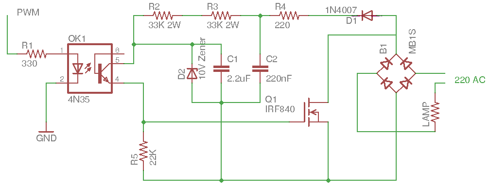
The circuit has an opto-isolator, which is a very important safety feature: it isolates the high voltage dimmer circuit from the PWM source, which is the ESP8266. So, here you can see that the two points where we connect to the high voltage AC power grid are isolated. We have magnetic coupling in the PSU (transformer) and optical coupling in the dimmer (opto-isolator). This is very important from a safety stand point.
One thing to be mindful of is the correct power rating of the components. Especially R2 and R3, which are used to feed the MOSFET gate: when the switch is off they will develop a voltage of around 128V around them (with a 230V mains), meaning they will have to dissipate around 0.5W. To be safe and make sure they last a long time, I’m using 2W resistors. And even still, they get pretty hot (but don’t touch them if you don’t like getting shocked!). Another consideration about this circuit is that as the duty cycle approaches 100% the MOSFET will starve itself, since it is effectively short circuiting the gate power supply. The maximum duty cycle is approximately 94%, so it’s a good idea to limit it in software to avoid instability. Also, as the voltage drops Q1 will start to go out of saturation which in turn increases resistance and generates a lot of heat, and heat is bad (unless you’re building a toaster).
The Incredible Tale of Gamma Correction
Did you know our eyes/brains don’t respond linearly to brightness? We perceive changes in low light better than we do when it’s bright. We evolved that adaptation: it’s more important to be able to see a lion in the bushes at night (or a robber in a dark alley) than to see the outline of the sun. That’s because our eyes, amazing as they are, don’t have an infinite dynamic range. That nonlinearity in our vision is caused by our pupils. They dilate when it’s dark, and contract when it’s too bright. I wanted the lamp to simulate a sunrise that looked linear: otherwise it would wake you up much too quickly. So, I made a transfer function to account for the nonlinearity, it’s the red line in the chart. The blue line represents the linear perception:
![]()
The wake-up functions progresses from pitch black to maximum brightness in 30 minutes. I made a time-lapse video of it so you can see how it looks like. It’s interesting to note that I had to fix the exposure. Without it the camera compensates and you can’t see it change at all. Here it is:
If you want to read bit more about the subject of gamma correction, Adafruit has a nice write-up here.
The ESP8266
Alright, so all the magic happens with the ESP8266 pulling the strings. These are some of the things included in the code:
- Connecting to a previously connected WiFi AP, showing a captive portal if not successful
- Advertising it’s own name and IP address using mDNS so that no IP configuration is necessary in the app (also known as Zeroconf or Bonjour for the Apple crowd)
- Synchronizing it’s own clock with a source of time from the Internet (periodically, as the clock drifts) and accounting for timezones and daylight savings time
- Serving Websockets connections and parsing commands from the Android app
- Processing commands to change the current brightness, toggle the audible alarm, toggle the sunrise function, set the alarm hour and days of the week
- Storing current settings on the EEPROM (if they changed), so they are preserved between power cycles
- Servicing the manual switch for toggling the light on an off and dismissing the alarm
- Generating PWM for the dimmer circuit for the desired brightness level (accounting for the nonlinearity described above)
- Smoothly fading in and out when the light is turned on and off
- Triggering the alarm and sunrise function when the day and time comes around
- Triggering the secret morse code message randomly with a given probability
The code is available on GitHub. Some of the libraries I used were a Websockets server and a WiFi captive portal.
The sound detection module is wired to a digital input and is serviced by a interrupt routine. That’s where the clap is debounced and the correct sequence and timing is evaluated. The PWM output that controls the dimmer is fed to the circuit shown above.
In the video below you can see the clapper in action. Make sure you have sound on!
The Android App
The Android app is a simple interface to control the lamp and all the functions available. I originally made it as a pure HTML5 application, but then I hit a snag: Android doesn’t automatically resolve mDNS names for it’s browsers. This has been discussed extensively and is supported on a system level in most platforms, including iOS/Safari, but for some weird inexplicable reason not on Android. It’s a very important feature, especially for IoT devices. But it is what it is, so I had to find a way around it. So I made it into an Apache Cordova app. Cordova is a framework for developing mobile apps based on HTML/JS that also gives you access to some low level functionalities like the camera and other sensors via libraries. In my case I needed it to receive mDNS broadcasts.
The app establishes a websocket connection, which is necessary for the dimmer to respond in real-time when the slider is moved. I could have used regular http requests but the user experience would be much worse.
The code for the app is also available on GitHub.
In the next video you can see the interface and the slider working. Unfortunately, the video doesn’t show the lamp changing it’s brightness perfectly. The reason for that is that I couldn’t fix the camera exposure while recording the screen at the same time. Check it out:
Wrapping Things Up
That’s what I had to share! Hope you found it interesting or useful. Some of the things that I might do in the future as improvements are to migrate the app to React Native to get a native look-and-feel and to get rid of a slightly annoying high frequency whining that I’m guessing is a harmonic frequency from the 400Hz PWM. By the way, I couldn’t get past 400Hz as the switching frequency, I think the optocoupler isn’t fast enough.
Your comments are welcome! 🙂
9 Comments